Basic switch and end device configuration
Learning basic switch and end device configuration in the network lab.
Devices used: 2 PCs and 2 switches
Additional resources: Console cables and ethernet cables
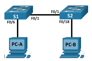
Topology

In this lesson we covered how to build a simple network using two hosts and two switches. We configured basic settings including hostname, local passwords, and login banner. I assigned IP addresses to both the PCs and switches to allow communication between the devices and pinged them using Windows Command Prompt to verify connectivity. It's important to make sure that the switches are erased and have no start-up configurations.
This task has really helped me develop my problem solving, communication, attention to detail and time management skills. Time management has been a big one as I have a timed practical exam coming soon at the start of January so I've been building small networks in my spare time and timing myself to make sure I can do in the allocated time.
Step 1:
Powering on all the devices and plugging in the cables by following the network topology above. I found the easiest way to do this was to start with PC-A and follow along the route until you get to PC-B.


I'm using the A2 and A3 ports on PC-A to configure both the switches by simply swapping the blue console cable over when needed. I found this easier as I only have to use one PC to configure the switches.


Step 2:
Assigning static IP address information to both PCs according to the addressing table shown above. Going into Control Panel > Category view > View Network status and tasks under Network and Internet heading > Change adapter settings.
Find Internet Protocol Version 4 (TCP/IPv4) in the list and click properties. Enter the IP address and subnet mask. Default gateway can be left empty as there aren't any routers in this network. Click OK and close all the windows to make sure it has saved.
Now both PCs have been assigned this information, I went to Command Prompt and typed "ipconfig" to check the status. Now to ping PC-B from PC-A by typing in "ping 192.168.1.11". 4 packets should be sent and received successfully. If this doesn't work then sometimes you have to disable Windows Firewall.
Step 3:
I'm using * to show comments. Using the PuTTY program on PC-A, I typed "enable" and pressed Enter. This should change Switch> to Switch#. This indicates the user is in privileged EXEC mode. Now to go into configuration mode.
Switch# configure terminal *goes into configuration mode so now shows Switch(config)#
Switch(config)# hostname S1 *changes the switch name to S1 according to the addressing table
S1(config)# no ip domain-lookup *prevents the switch from attempting to translate incorrectly entered commands as though they were hostnames.
S1(config)# enable secret class *assigns "class" as priv EXEC password
S1(config)# line con 0
S1(config-line)# password cisco *assigns "cisco" as console password
S1(config-line)# login *challenges for password
S1(config-line)# exit
S1(config)# interface vlan 1 *configuring switch virtual interface
S1(config-if)# ip address 192.168.1.1 255.255.255.0 *assigning IP address and subnet mask
S1(config-if)# no shut *turns on
S1(config)# banner motd @ text here @ *this makes a login banner to warn about unauthorised access. Make sure to use the same symbol before and after the message you want to show.
S1(config)# exit *this goes back to priv EXEC mode.
S1# copy running-config startup-config *this saves running config to the startup file on the non-volatile random access memory (NVRAM) where information can be stored even when the device is turned off.
S1# show running-config *this shows the entire running config. I found holding spacebar is helpful to advance the pages quickly :)
S1# show version *this displays the IOS version that the switch is running, along with other information.
S1# show ip interface brief *this shows the status of connected interfaces in a list
All I had to do now was to swap the console cable from the A2 to A3 port and repeat steps 2-3 to configure switch 2 using the network topology diagram and the addressing table. Key differences being the hostname and IP address.
To test that all the devices have been successfully configured for use you can use pings.


